#Adafruit trinket 5v wiring for lights code#
This sketch is an edited version of the Adafruit Neopixel Strand Test example code from the Neopixel Library. PomPom headband by Melissa Felderman for SparkFun Program your Arduino by uploading the example code provided below. If you are unfamiliar with uploading a program to your Arduino or the library installation process, please visit this tutorial on installing and using the Arduino IDE, and this tutorial on installing Arduino Libraries. Both boards output a digital endstop signal, and are intended to be wired to the three. If you can live with having all three FSRs wired in parallel into one analog channel, then the Trinket will suit your needs. Always check the to make sure that all your parts are correctly oriented before soldering together a circuit. If someone wants independent LED outputs for debugging, JohnSLs board should be your choice. The battery is also polarized it has a positive and negative side. The 5V version can run at 8 MHz or at 16MHz. If hooked up incorrectly, the LEDs will not light up. Use the 5V one for sensors and components that can use or require 5V logic. It's important to keep in mind that certain electronic components have polarity, meaning electric current can only flow through them in one direction. Their ability to interact with the real world by way of sensors and other electronics makes them ideal for automation such as.

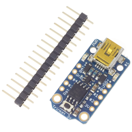
light up LEDs, and even talk to one another. We used a 47Ω resistor labeled with the yellow-purple-black bands. The Adafruit Trinket M0 is a powerful, yet tiny, microcontroller based on the Atmel ATSAMD21. Notice that the leads on the left of the LEDs (cathodes -) are connected to ground on the power source with a resistor.
Additionally, the negative leads will share another connection. DONT try that with other code includeThe bent leads on the right of the LEDs (anodes +) are connected to VCC on the power source and each other in red. When the LEDs are connected in parallel, all the positive leads will be connected together. Take a look at the LEDs, current limiting resistors, and battery in the circuit diagram below. In this circuit, the LEDs are soldered in parallel. In order to light the LEDs, electricity from the power source must flow from the positive (+) side of the battery through an LED and back to the negative (–) side of the battery. This electrical loop for the project is completed by soldering the LED's leads together. For our project, we’ll use LEDs (Light-Emitting Diodes). wires, traces, or any conductive materials), through one or more component(s), and then back to the power source. The beginner PomPom Headband project is an example of a basic circuit – an electrical loop that travels from a power source along a path (i.e.


 0 kommentar(er)
